Magnetic
Components cc


Planar Cores
Many next generation electronics equipment will use switched mode power supplies where the voltage transformation unit is intergrated on a circuit card.
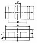
As cards may be racked with minimal clearances, low profile components are necessary. Planar assemblies differ radically from the conventional transformers as wire windings are replaced by stacks or flat spiral laminations.
In some cases the winding can be replaced by printing circuit tracks, with the E core inserted through the board. The planar E core's low profile shape and ease of constriction offers significant advantages including: Fast error-free winding; excellent heat sinking properties and effecient repeatable performance at low cost.
Part No. |
Core |
A mm |
B mm |
C mm |
D mm |
E mm |
F mm |
G mm |
le |
Ae |
Ve |
F44 |
F48 |
F47 |
|---|---|---|---|---|---|---|---|---|---|---|---|---|---|---|
| 32-9140- | EE14x3.5x5 | 14 ±0.3 |
3.5 ±0.1 |
4.9 ±0.2 |
11 ±0.25 |
2.9 ±0.15 |
2.05 ±0.15 |
- | 20.70 | 14.50 | 300 | - | - | 1100 ±25% |
| 32/33-9140- | E+l 14 | 14 ±0.3 |
- | 4.9 ±0.2 |
- | - | - | 1.50 ±0.05 |
16.70 | 14.50 | 240 | - | - | 1300 ±25% |
| 32-9180- | EE18x4x10 | 18 ±0.35 |
4 ±0.10 |
10 ±0.2 |
14 ±0.3 |
3.95 ±0.15 |
2.05 ±0.15 |
- | 24.30 | 39.50 | 960 | - | - | 2700 ±25% |
| 32/33-9180- | E+l 18 | 18 ±0.35 |
- | 10 ±0.2 |
- | - | - | 2.0 ±0.1 |
20.30 | 39.50 | 800 | - | 2900/R | 3100 ±25% |
| 32-9210- | EE22x5.7x15.8 | 21.8 ±0.4 |
5.7 ±0.1 |
15.8 ±0.3 |
16.8 ±0.4 |
4.9 ±0.2 |
3.20 ±0.1 |
- | 32.50 | 78.50 | 2550 | - | - | 4300 ±25% |
| 32/33-9210- | E+l 22 | 21.8 ±0.4 |
- | 15.8 ±0.3 |
- | - | - | 2.5 ±0.05 |
26.1 | 78.50 | 2040 | - | - | 5000 ±25% |
| 32-9320- | EE1.8x6.3x20.3 | 31.75 ±0.64 |
6.35 ±0.13 |
20.32 ±0.41 |
25.4 ±0.5 |
6.28 ±0.2 |
6.23 ±0.15 |
- | 41.70 | 129 | 5380 | 6425 ±25% |
- | 5900 ±25% |
| 32/33-9320- | E+l31.8 | 31.75 ±0.64 |
- | 20.32 ±0.41 |
- | - | - | 3.18 ±0.13 |
35.90 | 129 | 4560 | 7350 ±25% |
- | 6780 ±25% |
| 32-9380- | EE38.1x8.26x25.4 | 38.1 ±0.76 |
8.26 ±0.13 |
25.4 ±0.51 |
30.85 ±0.6 |
7.6 ±0.2 |
4.52 ±0.2 |
- | 52.60 | 194 | 10200 | 7940 ±25% |
- | 7250 ±25% |
| 32/33-9380- | E+l38.1 | 38.1 ±0.76 |
- | 25.4 ±0.51 |
- | - | - | 3.81 ±0.13 |
43.70 | 194 | 8460 | 9290 ±25% |
- | 8500 ±25% |
| 32-9640- | EE63.8x10.2x50.3 | 63.8 ±1.3 |
10.2 ±0.13 |
50.3 ±1 |
53.6 ±1.1 |
10.2 ±0.2 |
5.17 ±0.2 |
- | 79.70 | 511 | 40700 | 13300 ±25% |
- | 12120 ±25% |
| 32/33-9640- | E+l63.8 | 63.8 ±1.3 |
- | 50.3 ±1 |
- | - | - | 5.08 ±0.13 |
69.90 | 511 | 35500 | 15050 ±25% |
- | 14360 ±25% |
Part No. |
Core |
A mm |
B mm |
C mm |
D mm |
E mm |
F mm |
le |
Ae |
Ve |
F5 |
F9 |
F5A |
F44 |
F9C |
F10 |
|---|---|---|---|---|---|---|---|---|---|---|---|---|---|---|---|---|
| 32-580- | ETD29/16/10 | 30.6 -1.6 |
16 -0.4 |
9.8 -0.6 |
+1.4 22 |
9.8 -0.6 |
+0.6 10.7 |
70.4 | 76 | 5376 | - | - | 2350/R | 1950/R | - | - |
| 32-500- | ETD34/17/11 | +1 34 -0.6 |
-0.4 17.5 |
-0.6 11.1 |
+1.4 25.6 |
11.1 -0.6 |
+0.6 11.8 |
78.6 | 97.10 | 7640 | 2400/R | - | 2840/R | 2250/R | - | - |
| 32-520- | ETD39/20/13 | +1.1 38.9 -0.7 |
20 -0.4 |
12.8 -0.6 |
+1.6 29.3 |
12.8 -0.6 |
+0.8 14.2 |
92.20 | 125 | 11500 | 2700/R | - | 3210/R | 2470/R | - | - |
| 32-540- | ETD44/22/15 | +1.2 43.8 -0.8 |
22.5 -0.4 |
15.2 -0.8 |
+1.6 32.5 |
15.2 -0.8 |
+0.8 16.1 |
103 | 173 | 17800 | 3300/R | - | 3920/R | 3100/R | - | - |
| 32-560- | ETD49/25/17 | +1.3 48.5 -0.9 |
24.9 -0.4 |
16.7 -0.8 |
+1.8 36.1 |
16.7 -0.8 |
17.80 Mini |
114 | 211 | 24000 | 3700/R | - | 4400/R | 3525/R | - | - |
| 32-560- | ETD59/31/22 | 59.8 ±1.4 |
31.2 -0.4 |
22.1 -0.9 |
+2.2 43.6 |
22.1 -0.9 |
+0.9 22 |
139 | 368 | 51200 | 5000/R | - | - | 4900/R | - | - |
Part No. |
Core |
A |
B |
C |
D |
E |
F |
G |
le |
Ae |
Ve |
|---|---|---|---|---|---|---|---|---|---|---|---|
| 32-720- | EFD15x8x5 | 15 ±0.4 |
+0.15 7.5 |
4.65 ±0.15 |
11 ±0.35 |
5.55 ±0.2 |
2.4 ±0.1 |
5.3 ±0.15 |
34 | 15 | 510 |
| 32-740- | EFD20x10x7 | 20 ±0.22 |
10 ±0.15 |
6.65 ±0.15 |
15.4 ±0.5 |
7.75 ±0.2 |
3.6 ±0.15 |
8.9 ±0.2 |
47 | 31 | 1460 |
| 32-760- | EFD25x13x9 | 25 ±0.65 |
12.5 ±0.15 |
9.1 ±0.2 |
18.7 ±0.6 |
9.3 ±0.25 |
5.2 ±0.15 |
11.4 ±0.2 |
57 | 58 | 3300 |
RM Cores - Regular
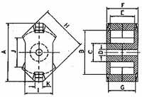
RM (Rectangular Modulus) cores arose due to the demand for coil formers with integrated pins that allow for efficient winding and high PCB packing densities. Clamps engaging in recesses in the core base hold the cores in place, meaning glue is not normally required in this process.
All the cores adhere to the specifications laid down in IEC 431 and in DIN 41980.
RM cores are designed for two main applications:
- Highly stable, extremely low loss filter inductors and other resonance determining inductors. (F58, P11)
- Low distortion broadband transmission at low signal modulation.
(F39, F10, F9)
RM cores can also be supplied without the centre hole. These have a higher A L value and cross sectional area and are used for power transformer applications. (F47, F44, F5A)
Dimensional Details
Part No. |
Core |
A mm |
B mm |
C mm |
D mm |
E mm |
F mm |
G mm |
H mm |
Σ√A |
le |
Ae |
Ve |
Approx. gms/set |
|---|---|---|---|---|---|---|---|---|---|---|---|---|---|---|
| 29-900- | RM4 | 11 -0.4 |
+0.3 8 |
3.9 -0.2 |
+0.1 2 |
+0.4 7 |
10.5 -0.2 |
+0.25 9 -0.25 |
9.8 -0.4 |
1.9 | 21 | 11 | 232 | 1.45 |
| 29-700- | RM5 | 14.6 -0.6 |
+0.4 10.2 |
4.9 -0.2 |
+0.1 2 |
+0.4 6.3 |
10.5 -0.2 |
+0.25 9 -0.25 |
12.3 -0.5 |
1 | 20.8 | 20.8 | 430 | 2.9 |
| 29-730- | RM6 | 17.9 -0.6 |
+0.5 12.4 |
6.4 -0.2 |
+0.1 3 |
+0.4 8 |
12.5 -0.2 |
+0.25 10.34 -0.25 |
14.7 -0.6 |
0.86 | 26.9 | 31.3 | 840 | 4.9 |
| 29-7600- | RM7 | 20.3 -0.8 |
+0.65 14.75 |
7.25 -0.3 |
+0.1 3 |
+0.4 8.5 |
13.5 -0.2 |
+0.25 11.3 -0.25 |
17.2 -0.7 |
0.74 | 29.8 | 40 | 1200 | 6.5 |
| 29-790- | RM8 | 23.2 -0.9 |
+0.6 17 |
8.55 -0.3 |
+0.2 4.4 |
+0.4 10.8 |
16.5 -0.2 |
+0.25 14.3 -0.25 |
19.7 -0.8 |
0.67 | 35.50 | 52 | 1850 | 10.3 |
| 29-830- | RM10 | 28.5 -1.3 |
+0.9 21.2 |
10.9 -0.4 |
+0.2 5.4 |
+0.6 12.4 |
18.7 -0.2 |
+0.25 16.2 -0.25 |
24.7 -1.1 |
0.5 | 42 | 83 | 3470 | 20 |
| 29-930- | RM12 | 37.6 -1.5 |
+1.1 24.9 |
12.8 -0.4 |
+0.2 5.4 |
+0.6 16.8 |
24.6 -0.2 |
+0.25 21.6 -0.25 |
29.8 -1.2 |
0.39 | 56.6 | 146 | 8340 | 44 |
| 29-980- | RM14 | 42.2 -1.2 |
+1 29 |
15 -0.5 |
+0.2 5.4 |
+0.6 20.8 |
30.2 -0.2 |
+0.25 27 -0.25 |
34.8 -1.3 |
0.35 | 70 | 200 | 14000 | 72 |
| 29-950- | R6 | 17.6 -0.6 |
+0.4 12.4 |
6.4 -0.4 |
+0.1 3 |
+0.4 8 |
12.5 -0.2 |
+0.25 10.34 -0.25 |
14.7 -0.5 |
0.8 | 25.6 | 32 | 820 | 5.1 |
AL Values with Tolerance Code
|
F58 |
P11 |
F5 |
F5A |
F5C |
F44 |
F47 |
F9 |
F9C |
F10 |
F39 |
F44A |
|---|---|---|---|---|---|---|---|---|---|---|---|---|
| Ungapped | - | 900R | - | - | - | 800R | - | 1700R | - | 2800R | 3700Y | 1100R |
| Ungapped | - | 1800R | - | - | 2600R | 1570R | - | 3170R | 6000Y | 5200R | 6700Y | 1800R |
| Ungapped | 890R | 2000R | 2250R | - | 3100R | 2200R | - | 4625R | 4270R | 6200R | 8600Y | 2200R |
| Ungapped | - | 2800R | - | 2850R | 3400R | 2370R | - | 4690R | 5040R | 7000R | 10000Y | 2700R |
| Ungapped | 1170R | 2500R | 3000R | 4000R | 4300R | 2906R | - | 5700R | 5670R | 8375R | 12500Y | 3300R |
| Ungapped | 1600R | 3960R | 4000R | 4490R | 3300+60% | 3800R | 3650R | 7600R | 8060R | 11000R | 16000Y | 4200R |
| Ungapped | - | - | 4400R | 5800R | 6000R | 5000R | 4750R | 8400R | - | 12800R | - | 5300R |
| Ungapped | - | - | - | 6600R | 6800R | 6000R | 5400R | 9500R | - | - | - | 6000R |
| Ungapped | 732R | 2300R | - | - | - | - | - | 4300R | 4900R | 6000R | 8600Y | - |
RM Cores - Low Profile
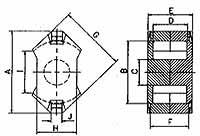
Low Profile RM Cores with the increasing miniaturisation of electronic circuits and Switched Mode power supplies being intergrated into PCB philosophy, low profile components are necessary to overcome height restrictions.
The RM core's low profile shape and ease of construction give significant advantages including, fast error free winding and efficient repeatable performance.
Dimensional Details
Part No. |
Core |
A mm |
B mm |
C mm |
D mm |
E mm |
F mm |
G mm |
Σ√A |
le |
Ae |
Ve |
Approx. gms/set |
|---|---|---|---|---|---|---|---|---|---|---|---|---|---|
| 29-210- | RM4 LP | 11 -0.4 |
+0.3 8 |
3.9 -0.2 |
+0.4 4.3 |
7.8 -0.2 |
+0.2 6.3 -0.2 |
9.8 -0.4 |
1.2 | 17.3 | 14.5 | 251 | 1.2 |
| 29-2100- | RM5 LP | 14.6 -0.6 |
+0.4 10.2 |
4.9 -0.2 |
+0.4 3.6 |
7.8 -0.2 |
+0.25 6.3 -0.25 |
12.3 -0.5 |
0.17 | 17.5 | 24.5 | 430 | 2.6 |
| 29-220- | RM6 LP | 17.9 -0.6 |
+0.5 12.4 |
6.4 -0.2 |
+0.4 4.5 |
9 -0.2 |
+0.25 6.84 -0.25 |
14.7 -0.6 |
0.58 | 21.8 | 37.5 | 820 | 4 |
| 29-230- | RM7 LP | 20.3 -0.8 |
+0.65 14.75 |
7.25 -0.3 |
+0.5 4.7 |
9.8 -0.2 |
+0.25 7.8 -0.25 |
17.2 -0.7 |
0.52 | 23.5 | 45.3 | 1060 | 5.7 |
| 29-240- | RM8 LP | 23.2 -0.9 |
+0.6 17 |
8.55 -0.3 |
+0.4 5.9 |
11.6 -0.2 |
+0.25 9.4 -0.25 |
19.7 -0.8 |
0.44 | 28.7 | 64.9 | 1860 | 9.2 |
| 29-250- | RM10 LP | 28.5 -1.3 |
+0.9 21.2 |
10.9 -0.4 |
+0.4 6.7 |
13 -0.2 |
+0.25 10.5 -0.25 |
24.7 -1.1 |
0.34 | 33.9 | 99.1 | 3360 | 17.2 |
| 29-260- | RM12 LP | 37.6 -1.5 |
+1.1 24.9 |
12.8 -0.4 |
+0.5 9 |
16.8 -0.2 |
+0.25 13.8 -0.25 |
29.8 -1.2 |
0.28 | 42 | 147.5 | 6195 | 33.6 |
| 29-270- | RM14 LP | 42.2 -1.2 |
+1 29 |
15 -0.5 |
+0.6 11.1 |
20.5 -0.2 |
+0.25 17.3 -0.25 |
34.8 -1.3 |
0.25 | 50.9 | 201 | 10230 | 55 |
AL Values with Tolerance Code
|
F44 |
F47 |
F48 |
F9C |
F10 |
F39 |
F44A |
F45 |
|---|---|---|---|---|---|---|---|---|
| Ungapped | - | - | - | - | - | 5000Y | 1200R | - |
| Ungapped | - | - | - | - | - | 7700Y | 2400R | - |
| Ungapped | 2500R | 2400R | - | 5500R | 6600R | 10500Y | 3000R | 2600R |
| Ungapped | - | - | 3120R | - | - | 11500Y | 3300R | - |
| Ungapped | 3600R | - | - | 7050R | - | 15000Y | 4100R | 3750R |
| Ungapped | 4700R | - | - | 10500R | - | 19500Y | 5200R | 4900R |
| Ungapped | 6000R | 5600R | - | 12750R | - | 23800Y | 6300R | 6300R |
| Ungapped | 6710R | 6280R | - | 16275R | - | 26640Y | 7100R | 7040R |
EE Cores
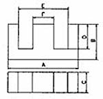
EE Cores were one of the first ferrite cores to be manufactured, being derived from their respective iron lamination size.
Having rectangular limbs they are relatively easy to manufacture and as such a vast range exists in the marketplace.
Magnecomp's range reflects a selection of cores that hace become, over many years, worldwide standards through continued use. EE cores are particularly suitable for power transformers and filters at low frequencies.
They are not suitable in high frequency applications as the rectangular centre limb leads to higher leakage inductance and winding resistance.
Dimensional Details
Part No. |
Core |
A mm |
B mm |
C mm |
D mm |
E mm |
F mm |
le |
Ae |
Ve |
F5 |
F9 |
F5A |
F44 |
F9C |
F10 |
|---|---|---|---|---|---|---|---|---|---|---|---|---|---|---|---|---|
| 32-200- | EF12.6 | +0.5 12.6 -0.4 |
6.5 -0.2 |
3.7 -0.3 |
+0.3 4.5 |
+0.6 8.9 |
3.7 -0.3 |
29.6 | 13.0 | 384 | - | - | - | 760/R | - | - |
| 32-040- | E13/6.6/3 | 12.7 ±0.25 |
6.6 ±0.05 |
3.18 ±0.2 |
5.105 ±0.155 |
9.725 ±0.725 |
3.18 ±0.2 |
31.70 | 9.68 | 307 | 550/R | - | - | - | - | - |
| 32-370- | E16/8/5 | +0.7 16 -0.5 |
8.2 -0.3 |
4.7 -0.4 |
5.7 +0.4 |
+0.6 11.3 |
4.7 +0.3 |
37.6 | 20.1 | 754 | 1000/R | 1400/R | - | 960/R | - | - |
| 32-140- | E20/10/5 | +0.7 20 -0.4 |
+0.1 10.1 -0.3 |
5.3 -0.4 |
6.5 ±0.2 |
13.1 ±0.3 |
5.00 ±0.2 |
43 | 31 | 1330 | 1500/R | 2500/R | - | 1390/R | - | - |
| 32-180- | EF20/10/6 | 20.4 -0.8 |
9.95 ±0.15 |
5.9 -0.4 |
+0.3 7 |
+0.6 14.1 |
5.9 -0.3 |
44.9 | 33.5 | 1500 | 1300/R | 2500/R | - | 1300/R | - | - |
| 32-160- | E19x8x5 | 19.3 ±0.5 |
8.085 ±0.115 |
4.75 ±0.18 |
5.75 ±0.125 |
14.5 ±0.53 |
4.75 ±0.18 |
40 | 22.5 | 900 | - | 2160/R | 1190/R | 970/R | 2350/R | 2650/R |
| 32-190- | E25/13/7 | +0.8 25 -0.7 |
12.8 -0.5 |
7.5 -0.6 |
+0.5 8.7 |
+0.8 17.5 |
7.5 -0.5 |
57.5 | 52.5 | 3020 | 1750/R | 3100/R | - | 1712/R | - | - |
| 32-030- | E25/9.5/6 | 25.4 ±0.63 |
9.53 ±0.13 |
6.27 ±0.2 |
6.49 ±0.19 |
19.56 ±0.51 |
6.27 ±0.2 |
48.70 | 38.10 | 1860 | 2000/R | - | 1830/R | 1480/R | - | 4000/R |
| 32-130- | E30/15/7 | +0.8 30 -0.6 |
-0.4 15.2 |
7.3 -0.5 |
+0.5 9.7 |
+0.8 19.5 |
7.2 -0.5 |
67 | 60 | 4000 | 1800/R | 3300/R | - | 1800/R | - | - |
| 32-010- | E34/13/8 | 34.14 ±0.86 |
13.11 ±0.1 |
7.87 ±0.18 |
8.485 ±0.205 |
24.59 ±0.63 |
11.12 ±0.25 |
62.50 | 77.4 | 4840 | 2240/R | 4100/R | - | 2360/R | - | - |
| 32-020- | E41/22/9 | 41 ±1.27 |
22.28 ±0.1 |
8.78 ±0.19 |
16.715 ±0.455 |
28.58 ±0.53 |
11.76 ±0.20 |
102 | 105 | 10600 | - | - | - | 2000/R | - | - |
| 32-110- | E42/21/15 | +1 42 -0.7 |
21.2 -0.4 |
15.2 -0.5 |
+0.6 14.8 |
+1.2 29.5 |
12.2 -0.5 |
97 | 181 | 17600 | 3500/R | - | - | 3500/R | - | - |
| 32-120- | E42/21/20 | +1 42 -0.7 |
21.2 -0.4 |
20 -0.6 |
+0.6 14.8 |
+1.2 29.5 |
12.2 -0.5 |
98 | 240 | 23300 | 4750/R | - | - | 4560/R | - | - |
| 32-150- | E55/27/21 | +1.2 55 -0.5 |
27.8 -0.6 |
21 -0.6 |
+0.8 18.5 |
+1.2 37.5 |
17.2 -0.5 |
120 | 354 | 42500 | 5800/R | 10000/R | - | - | - | - |
| 32-150- | E65/32/27 | +1.5 65 -1.2 |
32.8 -0.6 |
+0.6 26.8 |
+0.7 22.2 |
+1.5 44.2 |
20 -0.7 |
147 | 532 | 78200 | - | - | 10250/R | 7430/R | - | - |
| 32-250- | E70/32/32 | 70 ±1.35 |
+0.5 32 |
31.75 ±0.33 |
21.57 ±0.17 |
48.38 ±0.75 |
22.13 ±0.35 |
146.27 | 691.03 | 101076 | - | - | 11125/R | 9060/R | - | - |
Ferrite Toroidal
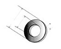
Ferrite toroids are ring-shaped components which can be used in a great variety of applications including EMI suppressors, chokes, transformers and inductors.
Toroids have many design advantages, for instance, they have a cross section which makes predicting electrical parameters a simple calculation.
The closed magnetic structure of toroids confines magnetic flux within the core body which gives the structure good shielding characteristics as well as optimal inductance to core volume ratio.
Magnecomp has a range of toroids in a wide range of materials and sizes from 2.03mm to greater than 100mm in diameter and that can be manufactured in any of the materials in order to optimize the part for a given application.
Click to download more information in pdf
 .
.
EMI Suppression and Other ferrites
Ribbon Cable Suppressors
Small Rods
Antenna Rods
Axial leaded Choke Cores
Impeder Welding Rods (Fluted)
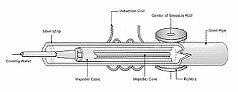
In high frequency tube welding process, mild steel strip of specific width is passed through several sets of
steel rolls.
The steel strip is converted into an open seam tubular shape. At this stage, the tubular shape
is passed through a high frequency induction coil.
The coil works as a primary and the open seam tube acts as one turn secondary. The induced current density is highest at the edges and results into rapid heating of these edges.
The subsequent pressure rolls press the open red hot seams together to form a butt weld joint. Ferrite rods kept inside the tube aid the process of welding by improving its efficiency.