Magnetic
Components cc


Current and Voltage Transformers
Standard and Custom wound AC and DC current Transformers DC voltage isolating transformers and isolating amplifiers.
Closed Loop Hall Effect Current Transformers
Introduction
Closed Loop Hall Effect Current Transformers are widely used in a variety of applications requiring an accurate, fast response signal proportional to the current being measured. Products are available for Panel and PCB mounting covering primary currents up to 1500A and provide complete galvanic isolation between primary and measuring circuit.
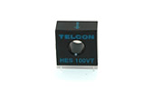
A more recent development is the HES range, which is a free standing detector coil assembly incorporating coil and Hall element only. This enables users to configure a Closed Loop Hall Effect Current Transformer to their own specification and to integrate the electronics within their own circuitry.
Operating Principle
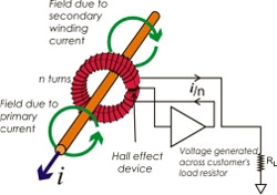
Closed Loop Hall Effect Current Transformers use ampere-turn compensation method to enable measurement of current from DC to high frequency with the ability to follow rapidly changing level or wave shapes. The application of primary current (lp) causes a change of flux in the air gap. This in turn produces a change in output from the Hall Element away from a steady state condition.
This output is passed through the secondary winding, causing a magnetizing force to oppose that of the primary current, thereby reducing the air gap flux. The secondary current will increase until the flux is reduced to zero.
At this point the Hall Element output will have returned to the steady state condition and the ampere turn product of the secondary circuit will match that of the primary.
The current that passes through the secondary winding is the output current. The transformation ratio is calculated by the standard transformer equation.
Applications
Current measurement for feedback control and over-current protection
- Variable speed drives
- UPS systems
- Process control and monitoring equipment
- Inverters and converters
- Power supplies
- Robotics
- Welding equipment
- Energy systems management
Features
- High accuracy
- Galvanic isolation between primary and secondary
- Covers AC, DC, and impulse current measurements
- Designed for ease of installation
- Wide dynamic range
- Non invasive (except NP style)
PCB Mounting
HTP 25 NP |
HTP 50 NPS |
|
|---|---|---|
| Nominal Primary Current | 25A |
50A |
| Supply Current | 14mA per rail + output current |
14mA per rail + output current |
| Min. Load Resistance | 100W |
90W |
| Linearity Limit | ±36A peak |
±75 A peak |
| Ratio Error | 0.5% of nominal primary current |
0.5% of nominal primary current |
| Bandwidth (1 dB) dc to | 150kHz |
150kHz |
| di/dt following | >100A/μs |
>100A/μs |
| Cable Configuration | integral primary |
integral primary |
HTP 25 NP |
HTP 50 NPS |
|
|---|---|---|
| Nominal Primary Current | 25A |
50A |
| Supply Current | 16mA per rail + output current |
16mA per rail + output current |
| Min. Load Resistance | 150W |
75W |
| Linearity Limit | ±55 A peak |
±80 A peak |
| Ratio Error | 0.5% of nominal primary current |
0.5% of nominal primary current |
| Bandwidth (1 dB) dc to | 100kHz |
150kHz |
| di/dt following | >150A/μs |
>200A/μs |
| Cable Configuration | integral primary |
integral primary |
HTP 100 & HTP 100/2K |
HTP 100S & HTP100S/2K |
|
|---|---|---|
| Nominal Primary Current | 100A |
100A |
| Supply Current | 16mA per rail + output current |
16mA per rail + output current |
| Min. Load Resistance | 45W |
45W |
| Linearity Limit | ±55 A peak |
±80 A peak |
| Ratio Error | 0.5% of nominal primary current |
0.5% of nominal primary current |
| Bandwidth (1 dB) dc to | 200kHz |
200kHz |
| di/dt following | >200A/μs |
>200A/μs |
| Cable Configuration | integral primary |
integral primary |
Panel Mounting
The HT range of Hall Effect Current Transformers is suitable for panel mounting, for measurement currents up to 300A
HT100 & HT100/2K |
HT200 |
HT300 |
|
Nominal Primary Current |
100A |
200A |
300A |
Supply Current |
16mA per rail + output current |
||
Min. Load Resistance |
0W |
0W |
0W |
Measurement range |
200A peak |
400A peak |
500A peak |
Overall accuracy |
1% of nominal primary current |
||
Bandwidth (1 dB) dc to |
100kHz |
100kHz |
100kHz |
di/dt following |
>100A/μs |
>50A/μs |
>50A/μs |
Cable Configuration |
through-hole |
||
Detector Coil Assembly
The HES range is a Hall Element and coil assembly enabling the implementation of a full Hall Effect Current Transformer by the addition of the requisite electronic circuitry, suitable for currents up to 100A. The range is available in both vertical (VT) and horizontal (HR) mounting. Full details of recommended electronic circuitry available on request. Typical performance with recommended circuitry is as follows.
HES 50VT |
HES 100VT |
||
Nominal Primary Current |
50A |
100A |
|
Coil Resistance |
52Ω |
32Ω |
|
Linearity Limit |
±80 A peak |
±140 A peak |
|
Ratio Error |
0.5% nominal primary current |
||
Bandwidth (1dB) dc to |
100kHz |
100kHz |
|
di/dt following |
>100A/µs |
>50A/µs |
|
Cable Configuration |
through-hole |
||